Please turn in your homework on paper.
Handwritten work is OK and probably much easier for you due to the math notation
and symbols.
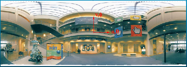
1) Suppose we are given a full spherical panoramic image, such as this one made by Richard Szeliski from Microsoft (from SIGGRAPH1999 course):
This rectangular grid of pixels holds equal steps in azimuth (theta)
horizontally, and elevation (phi) vertically, with theta changing from 0 on the
left side to 2pi on the right side, and phi changing from -pi/2 on the bottom to
+pi/2 on the top edge (I think the example image above is missing a few scanlines on the
bottom). Define the size of this
spherical panorama image as (u_max, v_max) spherical pixels.
Now suppose I want to convert this image to the 'cross-box' representation,
where each of the six panels of the cross-box holds a square grid of (cb_max,cb_max)
pixels. We can do this by warping in P2; every pixel in the spherical
panorama has a position in P2 given by (x1,x2,x3), and is a point on a sphere
around the origin.
1a) For any pixel (u,v) in a
spherical panorama (0<=u < umax, 0<=v<vmax, such as the one
shown above), write equations that will find its position (x1,x2,x3) on a sphere
around the origin in P2. In other words, find the functions x1(u,v)
,x2(u,v) and x3(u,v).
1b) For any pixel (a,b) on the front side
of the crossbox (0<=a<cb_max, 0<=b<cb_max), write equations that
find position (x1,x2,x3) in P2. In other words, find the functions x1(a,b),
x2(a,b) and x3(a,b). Similarly, write equations for the left, right, back,
and top, and bottom sides of the box. (This should be very easy).
Now suppose we warp the spherical panorama to make each of the six sides of a 'cross-box'. Assume that the spherical image above is actually a 2D texture map on a rectangular grid of vertices so that each pixel has a corresponding vertex with its own color. We can warp the 2D image by changing the 2D coordinates of each vertex, and OpenGL texture mapping will properly interpolate colors between these vertices.
1c) Find the location(s) on the cross-box panels
where will you find the highest density of spherical-panorama pixels: the
cross-box image will look its sharpest and best focused here.
How much will (a,b) change if we move one spherical pixel in
the u direction (e.g. what's the distance from (u,v) to (u+1,v) measured in (a,b)
units?) How much change do we get between (u,v) and (u,v+1) ?
1d) Similarly, find the location(s) of the lowest
density of spherical panorama pixels. The cross-box will look most blurry
here. How much will (a,b) change here if we move 1 pixel in the u
direction? in the v direction?
2) In class we reviewed light probes made from a
small convex spherical mirror, or 'mirror ball', photographed by a camera placed
at a
distance from the ball that is much greater than the ball radius. If the camera is far enough
away, we can approximate it as orthographic--in other words, rays from the
camera to any point on the ball are parallel; the mirror ball is in the 'far
field' of the camera. 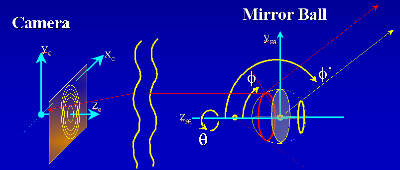
This 'far field' approximation permits a simple conversion
from camera image to 'rings' on a spherical panorama. As shown in this diagram,
we parameterize both the ball and the spherical panorama by angles theta and
phi, (think of the ball as a globe; aim the 'north pole' at the camera. Varying
theta from 0 to 2pi traces out rings of constant latitude, concentric around the
north pole. Angle phi is zero at the north pole, and increases to pi at the
south pole; think of phi as a 'ring selector').
2a) Suppose you have photographed
a mirror ball to make an image, and use (x,y) to describe position within that
image (0<=x<xmax, 0<=y<ymax, origin at lower left corner). If
the mirror ball center appears at (xc,yc) and its radius in the image is r, find
the P2 conic matrix for the image that traces out the image of the mirror ball
ring defined by angle phi. In other words, write C_ring(phi, xc, yc, r),
where C_ring is a 3x3 matrix.
2b) Now suppose the mirror-ball was in the
far field of the camera; thus phi' = 2*phi; in other words, the ring of camera
image colors for angle phi that you found in part 2a) becomes the ring of colors
for the mirror ball's panorama at angle phi'. (also shown in the diagram).
This simple phi' = 2*phi relation would allow you to construct a spherical
panorama at the mirror ball point as a collection of rings, but this is an
awkward way to describe the panorama. Instead, suppose you want to make the
front image of a box-cross panorama from a ring (the one between the camera and
the ball).
--What value of phi describes the largest ring that fits
completely within the front image of the box-cross panorama?
--Rings of constant phi form circles on the front image of a
box cross (provided that phi is not too large). If we define the size of a
box-cross image as width=height=1, then what is the radius of this circle as a
function of phi?
2c) Suppose our mirror ball is no longer in
the far-field of the camera. For a mirror ball with diameter d and a
camera of distance nd from the mirror ball, what is the relationship between
angle phi and angle phi'?
3) The Story: As part of a movie special-effects project, you built a gigantic 'CAVE' installation, a cubic room measuring 20 ft on each side
with seamless frosted-glass walls, floor and ceiling. Powerful video projectors
outside the room illuminate each wall with the 'box-cross' images computed in
problem 1.
The room includes a built-in 'Mission Impossible'-style
suspension harness rig to enable an actor hang in mid-air anywhere in the room,
suspended by nearly invisible cables. Powerful hidden cable motors enable
the actor to twist, rotate, and 'fly' anywhere in the
room.
To test everything, you put 150lbs of sandbags and a camera in the
harness, and then flew it around the room as you took many pictures. The
camera is a good one with no discernible distortions (e.g. perfectly planar, no
affine distortions). You mounted a bright, uniquely colored LED in each
corner of the room, placed at the exact intersection of the wall planes.
You also wrote a computer program that finds exact x,y coordinates for of the
LED spots visible in any photographs taken by the camera.
After the test session, your program found that Photos 34 and 89 show the same 4
LEDs at different positions, and these four LEDs define wall plane 'A'.
a) How would you crop these photos so they
show only wall plane A? Assume the 4 LEDs are obvious, but the edges of the wall
are not. Will the wall edges be curved or straight? if curved, write the
equation for the curve.
b) Each picture was taken from a different
3D (x,y,z) position and orientation (theta,phi). If we want to find the H
matrix that transforms photo 34 to photo 89 (after cropping in part a)), can we
use a P2 matrix (3x3), or must we use a P3 matrix (4x4)? Please explain your
choice.
4)Thinking/Discussion Question: Using the cube, camera, and motorized harness
you built in 3), suppose the camera is in an unknown position in the cube, but
you can change the orientation to look in any direction you wish (for
simplicity, assume the camera rotates about its center of projection). Suppose
the software that drives the projectors for each wall of the cube allows you to
draw lines at any desired position and orientation on the wall. You
can also 'clear' these lines to draw others.
a) Invent a method you could use to find
the position of the camera by drawing lines and aiming the camera. (A
text-only explanation of how you plan to do it is enough--math to prove that
your method works is not required).
b) Given the camera position, how would you find
its orientation, using only lines drawn by the projectors? Assume that you won't
always be able to see any of the LEDs.
c) Can you think of any way to make these
problems easier by drawing conics of some kind (besides the obvious: a line is a
degenerate conic, and so is a point)?