In this final project you will view and warp a 2D image into several 3D panoramas, and use the
viewer you made in Project 1 to display each of them. Your program
will:
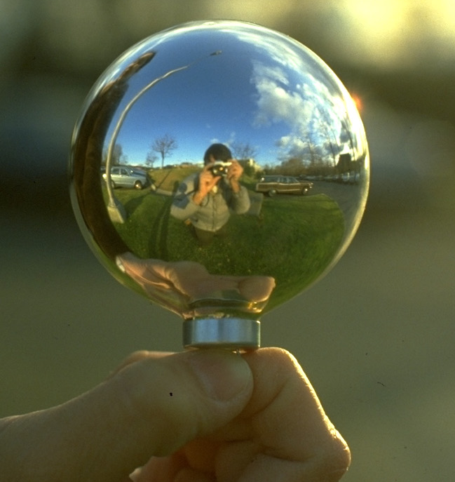
--- Read in a mirror ball or 'light probe' image that you like,
--- Find all the non-mirror-ball parts of the image and move
them out of the way,
--- Warp the image into the 3D half-sphere shape that caused
it,
--- Warp the half-sphere to form a full 3D sphere panorama,
--- Warp the sphere to make a cube panorama around the same
center point.
--- Design an interesting 2D warp of your own, and apply it to
the sides of the cube.
The work you did in Project 1 will then allow you to view any of the warps from any
angle or position.
User Interface: Trouble again. Your program needs to allow users to trigger or select each stage of your transformation (planar input image, matted, half-sphere, panorama sphere, panorama cube, 2D warps on cube surface). The best way would be a Windows/MFC user-interface widget of some kind, such as a drop-down menu, pushbutton, or perhaps open a different child window within the main window for each stage of the transformation. If MFC is too unfamiliar and troublesome, you may instead use a #define statement in one of your header (.h) files to choose one result, and submit multiple executable files along with your code; one for each display action.
Input Images: Look around on the web using terms like gazing orb, spherical mirror, spherical panorama, light probe, mirror ball panorama, etc. Here are ones I've found for you and converted as needed to Windows BMP format.
Probably the first 'light-probe' image ever used in computer graphics, by Gene Miller in 1982
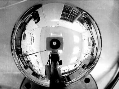
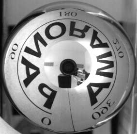
CZsvoboda.bmp
Two images from a Czech
panoramic imaging project,
CZsvoboda2.bmp
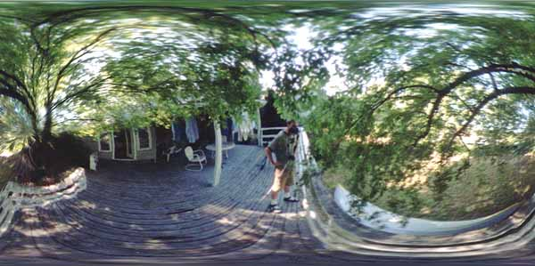
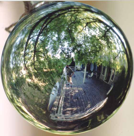
Here's an artist's
site showing an 'equirectangular' image that appears to be
an ordinary spherical mapping, with several to
choose from here. They used freely available 'PanoTools'
written in Java that are worth playing with; I think they originate with Dersh
here. Two images I like:
housedeck_flat.bmp,
and housedeck_src.bmp
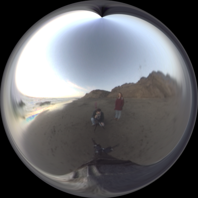
beach_probe.bmp
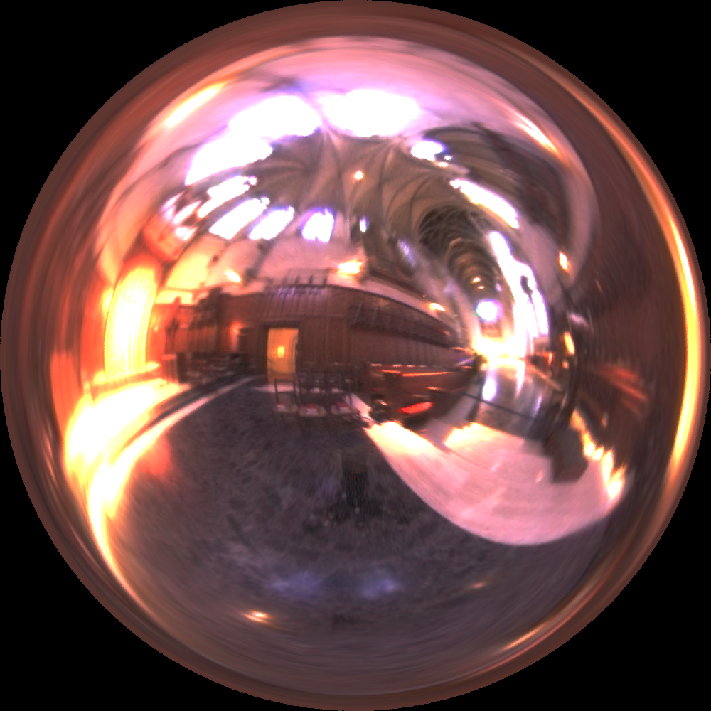
From the collection of light probe images from Paul Debevec's team.
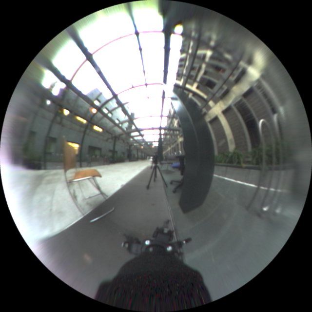
building_probe.bmp
Their website uses a high contrast 'HDR' format, and use their very nice
Galileo_probe.bmp
downloadable HDR format viewer to choose exposure settings, as I did here.
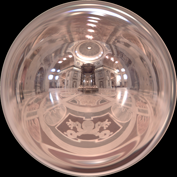
Grace_probe.bmp
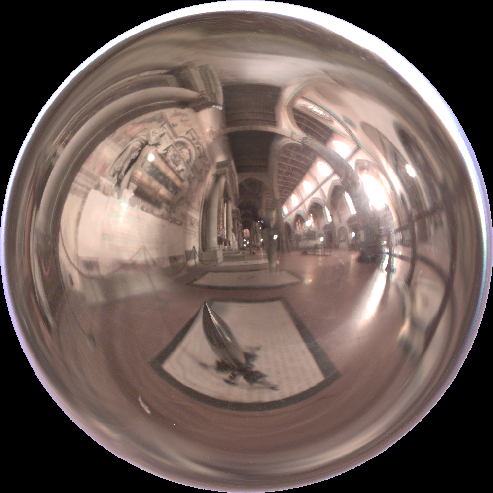
StPeters_probe.bmp
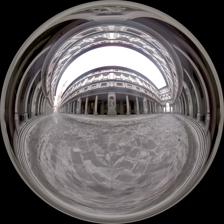
Uffizi_probe.bmp
Here's a Cylindrical Panorama Page has some beautiful (but non-spherical) input images too. Another site for some beautiful cylindrical panoramas from Germany.
At this site, Jonathan Cohen of ICT uses light probes as inputs and finds synthetic light source intensities and locations that will reasonably simulate the lights.
Photoshop plugin for mirrorball images, complete with a tutorial on how to remove the photographer from the scene by photographing the ball twice, from 2 different angles.
---1) View: Be sure your Project 1 code can read in a BMP file that holds a mirror-ball image, and
display it as a texture map on a planar grid of OpenGL vertices. You should be able to 'click-drag' the mouse to make 3D viewing
changes for that plane.
If you wish, your program may use 'hard-coded' constants for image size (xmax,ymax), for grid size, and for the
center an the radius of the image of the mirror ball, but these should be set by
#define statements in one of your header (.h) files and clearly marked, so that
it is easy to adjust or modify them for a different image.
(Never put numerical constants in your code that depend on user preferences or input
images).
---2) Matte: Find all the image vertices that are not a part of the
mirror ball, and move them out of the way. For example, if the image
vertices are at location (x,y,0), you could change the 3D coordinates of
all the vertices that fall within the mirror ball's radius to (x,y,1), and
all other the others to (0,0,0). This would move the mirror-ball part of
the image away from the origin and 'gather together' all the unwanted vertices
at the origin, forming a cone-like shape in 3D.
---3) Half-Sphere Warp: Construct a half-sphere colored by the
light probe image.
For each mirror-ball vertex,
a) Convert rectilinear image grid coordinates (x,y)
to polar coordinates (r, theta) in the image.
b) Convert these polar coordinates to spherical
coordinates of the mirror ball. For simplicity, assume the mirror-ball
image is orthographic, e.g. that rays from the camera to the mirror ball surface
are parallel, so the distance from the mirror ball to the camera that
photographed it doesn't matter, and center the sphere at the origin.
Thinking in 3D now (see figure in
Homework 2), convert (r,theta) to spherical coordinates on the
mirror ball (phi,theta), where phi is latitude and theta is longitude (phi=0 at
the north pole, pi at the south pole). Remember that when r=0 we have a
zero-diameter circle on the image that matches a zero-diameter circle around the 'north
pole' of the sphere. Increasing radius r from zero corresponds to
increasing 'longitude' phi from zero on the mirror ball sphere; find the mapping
from r to phi.
c) Move the vertex in 3D; place it at angular position
(phi,theta) on a sphere around the origin. You'll need to figure out how
to convert spherical coordinates (phi,theta,r_s) to Cartesian coordinates (x,y,z).
Now the previously planar grid image
has become a textured half-sphere shape in 3D: its colors are the image colors mapped to the mirror ball points
that reflected them to the camera.
---4) Panoramic Sphere Warp: Move the vertices again to change
a half-sphere to a full sphere panorama:
For each mirror-ball vertex,
a) find the vertex position in spherical coordinates (or just
remember it from step 3) as (phi, theta, r_s).
b) Though the vertex hold colors that were SEEN on the mirror
ball at this position, it these light values did not arrive at the mirror ball
from the (phi,theta) directions from the environment. As
discussed in class, the incoming light direction is phi'=2*phi, and theta,r_s
are unchanged. Accordingly, find the new 3D position (phi',theta,r_s) for
each vertex.
c) Convert to x,y,z position, and move the vertex there.
Now your previously planar grid image
has become a textured sphere shape, with a funny little 'dent' at the back where
vertices not on the mirror sphere have collected at the origin.
---5) Panoramic Cube Warp: Move the vertices again to change a
sphere to an axis-aligned cube:
For each mirror-ball vertex,
a) Use its (x,y,z) coordinates to determine its cube
face. Test the coordinates to do this; results of (|x|>|y|),
(|y|>|z|), (|z|>|x|) and sign of x,y, or z will determine whether to put
the point on the front (x=+1), back(x=-1), top(z=+1), bottom(z=-1) etc.
b) Move the point radially outwards from the sphere center to
its position on a cube face.
---6) 2D Free-Form Plane Warp: For each side of the cube, make an interesting warp of your own design. This can be any interesting rearrangement of the points, but the result must still have points constrained to the cube surface planes. One interesting class of warp to consider would first change vertex positions in 3D, then transform them back to 2D using a projective camera matrix as described in Chapter 5. In example shown in class, a flat 2D field of circles was warped in 3D by a sinusoid, then projectively viewed at an angle to give the appearance of endless polka-dotted waves that stretch towards the horizon.
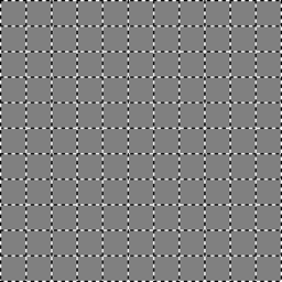
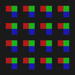
You may wish to test your program using these simple grid-like test images to help understand the geometric changes made by your program.