The research reviewed in the previous section concentrated on generating aesthetically pleasing images. The work done by Seligmann and Feiner [34], Winkenbach et al. [39], Saito et al. [29], Land et al. [22], Elber [13], and Dooley et al. [11] generated images in which the primary goal is to convey shape information. However, these techniques generate single images and do not allow user interaction.
Seligmann and Feiner [34] created a system based on the idea that an illustration is a picture that is designed to fulfill communicative intent. They assert that the purpose of illustration is to show an object's material, size, orientation, and, perhaps, how to use it. The purpose is not only to display geometric and material information but to also provide the viewer information about the object's features, physical properties, and abstract properties. ``Illustration objects are generated based on both the representation of the physical object as well as the communicative intent''(p. 131), i.e., the images must convey the geometric characteristics as well as the purpose of each of the objects, such as which way to turn a dial on an image of a radio. Their ``Intent-Based Illustration System'' (IBIS) uses a generate-and-test approach to consider how the final illustration will look. For each illustration, there are several methods and several evaluators. By performing the permutations of the methods and then evaluating them by the ``rules,'' IBIS automatically generates the image that would look ``best.''
|
|
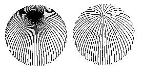
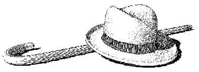
| Figure 2.3: One-shot computer-generated pen-and-ink images conveying shape by Winkenbach. Copyright 1996 Georges Winkenbach [39]. Used by permission. | |
Winkenbach et al. [39] renders a single pen-and-ink style image for parametric free-form surfaces, using ``controlled-density hatching'' in order to convey tone (intensity), texture and shape, as shown in Figure 2.3. Their paper provides a highly detailed algorithm on drawing lines (strokes) which gradually disappear in light areas of the surface or where too many lines converge. They use a planar map constructed from the parametric surfaces to clip strokes and generate outlines. The planar map is not constructed from 3D BSP Trees, but by the following method. They tessellate every object and then compute the higher-resolution piecewise linear approximations for all silhouette curves of meshed objects, similar to Elber and Cohen [13], whose work is discussed in Section 2.3. The planar map is created by determining which mesh faces are closest to the view. They then use 2D BSP trees to implement shadows [6].
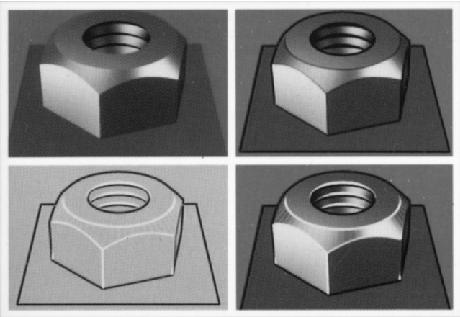
Saito and Takahashi [29] offer convincing pictures to show how 3D models enhanced with discontinuity lines, contour lines, and curved hatching can generate images which convey shape and structure, as shown in Figure 2.4. They propose ``new rendering techniques to produce 3D images with enhanced visual comprehensibility,'' realized with 2D image processing. They construct a data structure called G-buffer, which preserves a set of geometric properties. If shapes and camera parameters are fixed, any combination of enhancement can be examined without changing the contents of the G-buffer.
|
| Figure 2.4: Another example of one-shot image conveying shape. Saito enhances a shaded model by drawing discontinuity and contour lines. Copyright 1990 Saito [29]. |
Land and Alferness [22] present a method for rendering 3D geometric models as black and white drawings. They compute Gaussian and mean surface curvatures of objects and allow the user to threshold, combine, and modify these curvatures. They produce images that contain shape information that is independent of orientation or illumination. They state that, perceptually, humans are good at inferring shape from line drawings, ``Lines which approximate lines of curvature may be particularly effective indicators for humans''(p. 2).
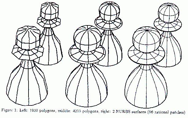
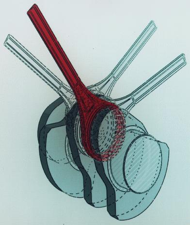
Elber [13] provides surface information with four types of curves: the surface boundary curves, curves along C1 discontinuities in the surface, isoparametric curves, and silhouette curves, as shown in Figure 2.5(a). All of the above curves except silhouette curves are view-independent and only need to be calculated once per model. Silhouette curves are calculated by normalizing the view orientation so that the view is on the positive z-axis at infinity and the image is projected onto the plane z=0. Elber defines a silhouette point as a point on the surface whose normal has a zero z-component. The silhouette curve of the surface becomes the set of silhouette points forming a continuous curve. When a C1 discontinuity is found in a surface, Elber divides the surface into two surfaces. Elber's methods cannot be applied directly in an interactive system, because the method uses costly ray-surface intersection calculations to determine visibility. I build upon his observations, using a different method to calculate silhouettes in order to achieve interactive rates.
|
|
| Copyright 1990 Gershon Elber~\cite{elbe90}. Used by permission. | Copyright 1990 Debra Dooley~\cite{dool90}. Used by permission. |
| Figure 2.5: One-shot images conveying shape by Dooley and Elber. | |
Dooley and Cohen [11] created an illustration system which used display primitives, such as transparency, lines with variable width, and boundary/end point conditions, as shown in Figure 2.5(b). Visibility information is gathered by ray tracing, which helps to communicate structure and illuminate unnecessary details and clutter. By establishing a user-defined hierarchy of components, users can define not only what they want to see but how they want to see it. However, in their implementation the camera model is then generated and for the rest of the process remains fixed. Most of time is spent ray tracing to gather visibility information, which is done separately for lines and surfaces. After the information on lines and surfaces is put together, illustration primitives are created, placed in an image buffer, and read by a scan-line renderer. No measurements of the time it took to generate the illustrations were given. The result is a 2D illustrated image which cannot be manipulated like a 3D model.