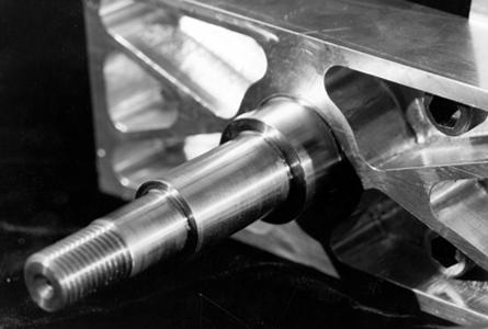
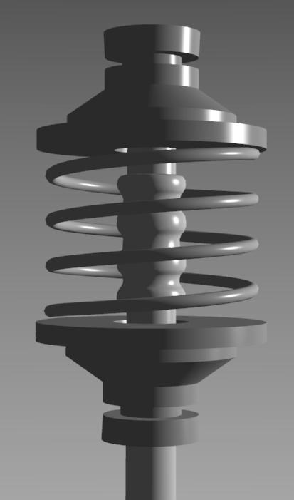
Illustrators use a different technique to communicate the surface properties of metallic objects, as shown in the photograph in Figure 21. In practice illustrators represent a metallic surface by alternating dark and light bands. This technique is the artistic representation of real effects that can be seen on milled metal parts, such as those found on cars or appliances. Milling creates what is known as ``anisotropic reflection.'' Lines are streaked in the direction of the axis of minimum curvature, parallel to the milling axis. Interestingly, this visual convention is used even for smooth metal objects [20,23]. This convention emphasizes that realism is not the primary goal of technical illustration.
|
| |
|
| |
|
|
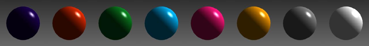
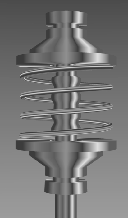
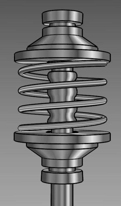
| Phong-shaded object. | New metal-shaded object without edge lines. |
|
|
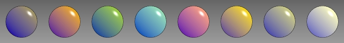
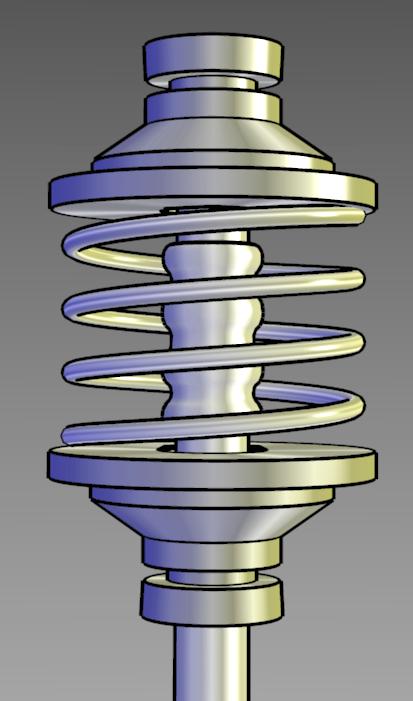
| New metal-shaded object with edge lines. | Metal-shaded object with a cool-to-warm shift. |
| Figure 4.24: Representing metallic material properties. | |
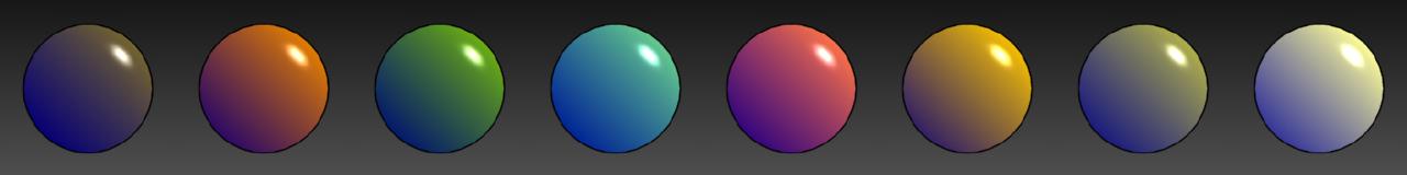
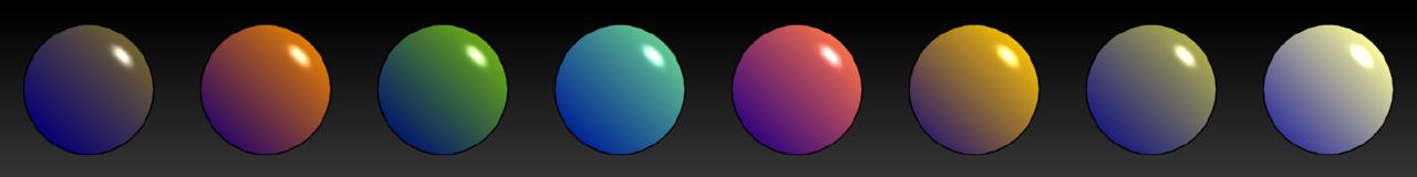
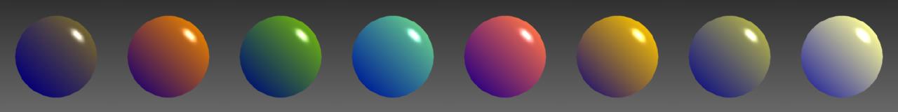
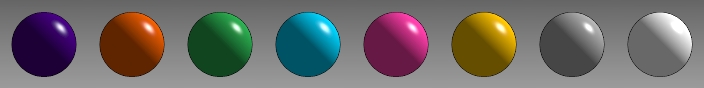
To simulate a milled object, Gooch et al. [11] maps a set of 20 stripes of varying intensity along the parametric axis of maximum curvature. The stripes are random intensities between 0.0 and 0.5 with the stripe closest to the light source direction overwritten with white. Between the stripe centers the colors are linearly interpolated. An object is shown Phong-shaded, metal-shaded (without and with edge lines), and metal-shaded with a cool-warm hue shift in Figure 22. The metal-shaded object is more obviously metal than the Phong-shaded image and the metal-shaded object with edge lines provides more shape information. The cool-warm hue metal-shaded object is not quite as convincing as the achromatic image, but it is more visually consistent with the cool-warm matte-shaded model of Section 8.4.2, so it is useful when both metal and matte objects are shown together. In Section 10 of the course notes, we will discuss how these techniques may need to change in an interactive system.