n(u,v), mesh
indices i and j, and the sign,
n(u,v), mesh
indices i and j, and the sign,  , of
(E . n). A 2D marching-cube data structure is necessary
for holding the silhouette points and assembling them into silhouette
curves. The 2D marching-cube data structure contains four control
points and their (u,v) values, as well as a list of possible
silhouette points (four are possible between the mesh points with four
additional points possible at the mesh points).
, of
(E . n). A 2D marching-cube data structure is necessary
for holding the silhouette points and assembling them into silhouette
curves. The 2D marching-cube data structure contains four control
points and their (u,v) values, as well as a list of possible
silhouette points (four are possible between the mesh points with four
additional points possible at the mesh points).
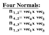
The algorithm is as follows. First find the normals at each of the control mesh points. For every mesh point, there are up to four possible normals that need to be calculated, n1,3, n1,2, n4,3, n4,2 as can be seen in Figure 4.2. This calculation only needs to be done once per surface; the rest of the calculations needs to be made every time the viewpoint changes.

|
| Figure 4.2: Calculating the mesh normals: The four mesh normals which correspond to mi,j are n1,3, n1,2, n4,3, n4,2, where for example n1,3 = vec1 x vec2, with vec1 = mi,j - mi-1,j and vec2 = mi,j-1 - mi,j. |
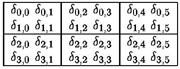
Next, classify each mesh normal based on the sign, , of E(u,v) . n(u,v). There are four signs per mesh point. For
example, a 4x3 control mesh can be visually represented and stored in
a table like Figure 4.3.
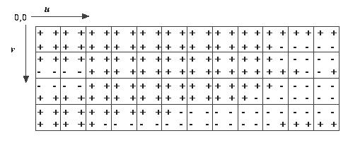
To define which set of signs signal a possible silhouette, I looked at
the combinations of 's stored in the table. The trick is in
determining what constitutes a possible silhouette. This method
creates a large number of sign group variations which can indicate
possible silhouettes, as can be seen by looking at the combinations of
pluses and minuses around each mesh point in
Figure 4.4(a). The implementation of this method
involves a large set of case statements, looking at the mesh and the
relative signs to determine where silhouettes may be.
Comparisons need to be made in both the u (mi,j and mi+1,j) and in the v (mi,j and mi,j+1) directions.
First check for  = 0. If = 0 then
interpolate based on the parametric values associated with
mi-1,j and mi+1,j to get the silhouette point on the
surface, if there is one.
= 0. If = 0 then
interpolate based on the parametric values associated with
mi-1,j and mi+1,j to get the silhouette point on the
surface, if there is one.
Next, check for changes between the mesh points in the u and v
directions, i.e., mi,j and mi+1,j, as well as mi,j and
mi,j+1. For example, this would mean looking at the two groups:
 in Figure 4.3.
There are four sign comparisons made per box in the 2D marching cube
data structure: for example, 
If a sign change is found, then the linear interpolation described in
Section 4.1.2.1 will provide a silhouette point at
u,v. The silhouette points are stored in the 2D marching-cube
structure. Silhouette points are turned into silhouette curves by
traveling though the marching cube data structure, connecting points
to form edges. The top image in
Figure 4.4 provides
a visualization of the
and Figure 4.5 the
approximate silhouette lines for the Mesh Method and the Srf-Node
Method. Figure 4.6 shows the
results of the Mesh Method on a surface. Using the Secant Method or Newton's Method, these edges can be
refined.
 Mesh Method
|
| Figure 4.4: These images show the control mesh (in uv-space) for a surface where +, -, or 0 denotes the sign of the dot product (E(u,v) . n(u,v)). For the Mesh Method, there are up to four dot products that need to be calculated per mesh point, only one per mesh point for Srf-Node Method. |
 Mesh Method
|
||
| Figure 4.5: These images show the control mesh (in uv-space) for a surface, with approximations to the silhouettes. The sign of the dot product (E(u,v) . n(u,v)) are denoted by +, -, or 0. | ||
 |

|
| View of surface with silhouettes generated with mesh method. | Looking down on surface with silhouettes. |
| Figure 4.6: Mesh Method. | |